Illustrations in preparation: reference examples from the previous stable release appear alongside placeholders for new captures.
Panel Line Designer (PLD)
User Manual — English
Version 2.0.21 — Public Trial
Release Date: October 2, 2026
Author: RENDA - TOKUGAWA ELECTRONICS.
1. Introduction
Panel Line Designer (PLD) is a Blender add-on that creates panel lines and recessed grooves with physical width and depth from selected mesh edges.
PLD does not use Boolean cutters or decals. It generates actual mesh geometry for the grooves.
PLD stores the original object and selected-edge information, allowing the result to be rebuilt while you adjust width, depth, junction handling, and finishing settings. Once you are satisfied with the result, you can finalize it as a regular editable mesh.
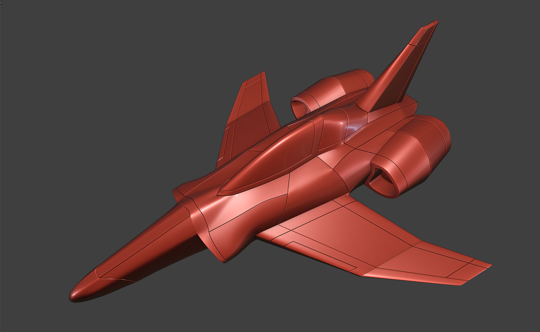 Overall
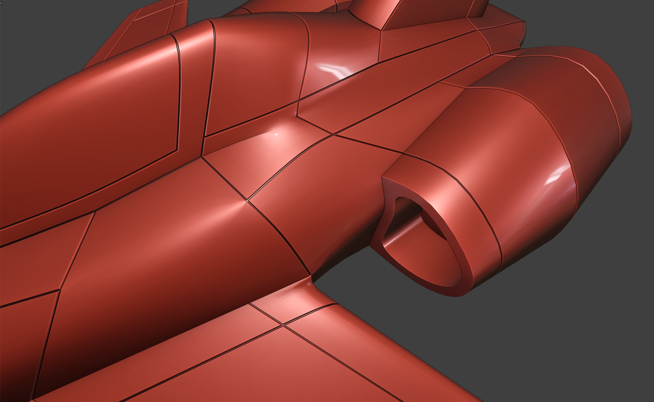 Curved surface
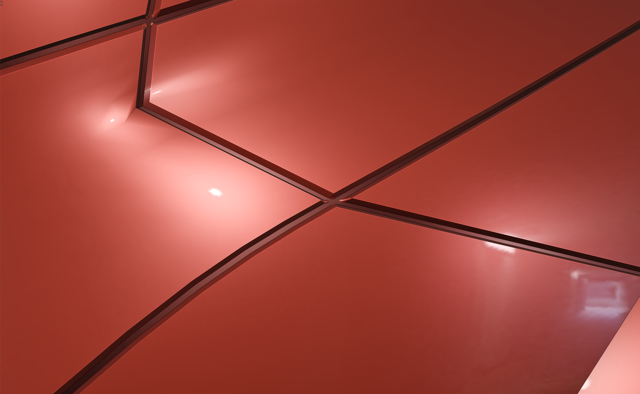 Groove floor
Supported Environment
- Target: Blender 5.1 series
- Minimum declared version: Blender 5.1.0
- Tested environment: macOS / Blender 5.1.2
- Blender 4.2 LTS: not supported by this release
- Installation package:
PLD_2.0.21.zip - Add-on format: Legacy Add-on
- Add-on folder:
panel_line_designer - License: GNU GPL v3 — see the included
LICENSE.txt
Operation on other operating systems, future Blender versions, or other untested environments is not guaranteed.
PLD 2.0.21 is based on the stable tapered-groove version of PLD. It is not the PLD-E / extrusion research version. This release streamlines panel-line regeneration by optimizing search routines and redundant calculations. Adjusting only Rim Rounding Width or Rounding Segments normally updates the modifier parameters without rebuilding the groove mesh, improving responsiveness during refinement. PLD falls back to rebuilding when required attributes are missing or a direct update is not possible.
2. Installation
- Extract the complete distribution ZIP you received.
- Locate
PLD_2.0.21.zipinside the extracted folder. Do not extract this installation ZIP. - Start Blender.
- Open Edit → Preferences → Add-ons.
- Choose Install from Disk.
- Select
PLD_2.0.21.zip, install it, and enable PLD. - Restart Blender.
If the older panel_line_designer_2 add-on is installed, disable it to avoid conflicts. Restart Blender after updating PLD as well.
In the 3D Viewport, press N to open the Sidebar. The PLD tab should appear there.
If PLD does not appear, check your Blender version, confirm that the add-on is enabled, and make sure the older add-on is disabled.
3. Creating Your First Groove
3.1 Select the Edges
- Select the mesh object where you want to create panel lines.
- Enter Edit Mode.
- Switch to Edge Select and select one or more edges.
- Open the PLD tab in the Sidebar.
PLD displays the current number of selected edges.
3.2 Create the Panel Lines
Click:
Create Panel Lines from N Selected Edges
where N is the current number of selected edges.
PLD records the selected edges, generates the groove, and manages the result as a separate object.
The original object is not deleted. It is moved to the:
PLD Backups
collection and retained as the source used for rebuilding the result.
After generation, the result object becomes active in Object Mode and its PLD settings can be adjusted.
Initial Settings
The property defaults for the main settings are:
- Groove Width: 0.02
- Groove Depth: 0.01
- Align Floor to Rim: 0
- Align Cross-Section Loops: 1
- Junction Finish: Standard
These are the property defaults. The actual values used when creating a new result may differ because PLD can reuse previous settings or values associated with your workflow or presets.
Start by adjusting Groove Width and Groove Depth for the scale and thickness of your model.
On thin wings, panels, or shells, excessive depth may intersect the opposite surface. Inspect the back side when necessary.
4. Rounding the Groove Rim
Round Rim softens the edges of a generated groove, creating edge highlights characteristic of manufactured parts. Use it to refine how light catches a parting line.
The rounding controls follow Blender’s interface language. Their Japanese and English labels are:
- 「フチを丸める」 — Round Rim
- 「フチの丸め幅」 — Rim Rounding Width
- 「丸めセグメント」 — Rounding Segments
- Select the generated PLD result.
- Open Finishing in the PLD panel.
- Enable Round Rim. It is off by default.
- Adjust Rim Rounding Width and Rounding Segments while checking the highlights from the same viewpoint.
「フチの丸め幅」 — Rim Rounding Width
Property default: 0.001
Minimum: 0.000001
This controls the bevel amount applied to the groove rim.
It is separate from Groove Width. Rounding changes the visible opening, so the apparent width after rounding is not guaranteed to remain exactly equal to the original groove-width setting.
「丸めセグメント」 — Rounding Segments
Property default: 5
Range: 1–16
Higher values produce a more finely segmented roundover but also increase geometry and processing requirements.
How Rim Rounding Works
PLD automatically manages a standard Blender Bevel modifier targeting a dedicated edge attribute, together with Geometry Nodes that supplements junction creases. The two stages combine rim rounding with crease control at connections.
The basic order is:
PLD Rim Bevel → PLD Rim Crease → Subdivision → Weighted Normal
Other modifiers may also exist, including modifiers inherited from the original object.
The managed Bevel targets PLD's dedicated edge attribute:
pld_rim_weight
The Geometry Nodes stage supplements crease information at generated connections such as T-junctions, crosses, and the outside of turns where a conventional bevel alone may leave the crease incomplete. The GN stage itself does not modify vertex coordinates or face connectivity.
The results of Line Turn Threshold and Surface Fold Threshold are carried through the rounding process.
If another manually configured Bevel is already affecting the same area, the groove may be processed twice. Check the purpose and target of each Bevel if unexpected rounding appears.
Disabling Round Rim removes the PLD-managed rounding modifiers. Short edges and dense junctions may require a smaller rounding width. Subdivision may change the original curvature; exact shape preservation is not guaranteed.
Adjusting overlap limits
Clamp Overlap on PLD Rim Bevel and Clamp Overlap in PLD’s advanced settings act at different stages. If the rim rounding is smaller than intended, first check rounding width and nearby edge spacing. Advanced users may compare the result with Clamp Overlap disabled on the modifier, but this can allow self-intersections. Recheck the modifier value after regenerating the groove or reapplying settings.
Adjust rounding through the PLD panel. Avoid manually changing managed attribute names, Bevel/GN settings, or Geometry Nodes groups. They are part of PLD's rebuilding system.
5. Re-editing and Finalizing
5.1 Change the Panel-Line Edges
Select the PLD result and click:
Reselect Panel-Line Edges
PLD returns to the original source mesh in Edit Mode.
To restore the edge selection stored by PLD, use:
Reselect Stored Panel-Line Edges
You can then add or remove selected edges.
When the selection is ready, click:
Apply Selected Edges
PLD records the new selection and rebuilds the result.
If the source topology has changed, PLD may no longer be able to identify some stored edges. Check the selection again after changing the source mesh.
5.2 Keep PLD Backups While Re-editing
The source object in PLD Backups is the basis for rebuilding an editable PLD result.
Do not delete the backup while you still need PLD re-editing.
Also avoid treating the generated result as a permanently hand-edited mesh before finalization. Changes made directly to result geometry may be lost when PLD rebuilds it.
5.3 Finalize Panel Lines
When the result is complete, enter Object Mode and click:
Finalize Panel Lines
Finalizing ends PLD procedural rebuilding and turns the current result into a regular editable mesh.
After finalization, Groove Width, Groove Depth, and the stored panel-line edge selection can no longer be changed through PLD.
The original object remains as a backup. This does not provide a way to return the finalized result to PLD procedural rebuilding.
Finalizing does not automatically apply Mirror, Subdivision, Bevel, Geometry Nodes, or other remaining modifiers.
PLD also does not automatically apply the original Subdivision modifier during groove generation or finalization.
To discard the generated PLD result instead, use:
Remove Panel-Line Setup
This deletes the generated result and restores the original object's collection membership and visibility state.
6. Settings Reference
6.1 Basic Settings
Groove Width
Controls groove width. Property default: 0.02.
Groove Depth
Controls how far the groove floor is recessed. Property default: 0.01.
Align Floor to Rim
Range 0–1, default 0. Corrects floor orientation and position relative to the rim. It does not guarantee exact depth or intersection avoidance.
Align Cross-Section Loops
Range 0–1, default 1. PLD automatically detects supported corresponding cross-section loops and adjusts their floor alignment. Some groove configurations may not qualify for this correction.
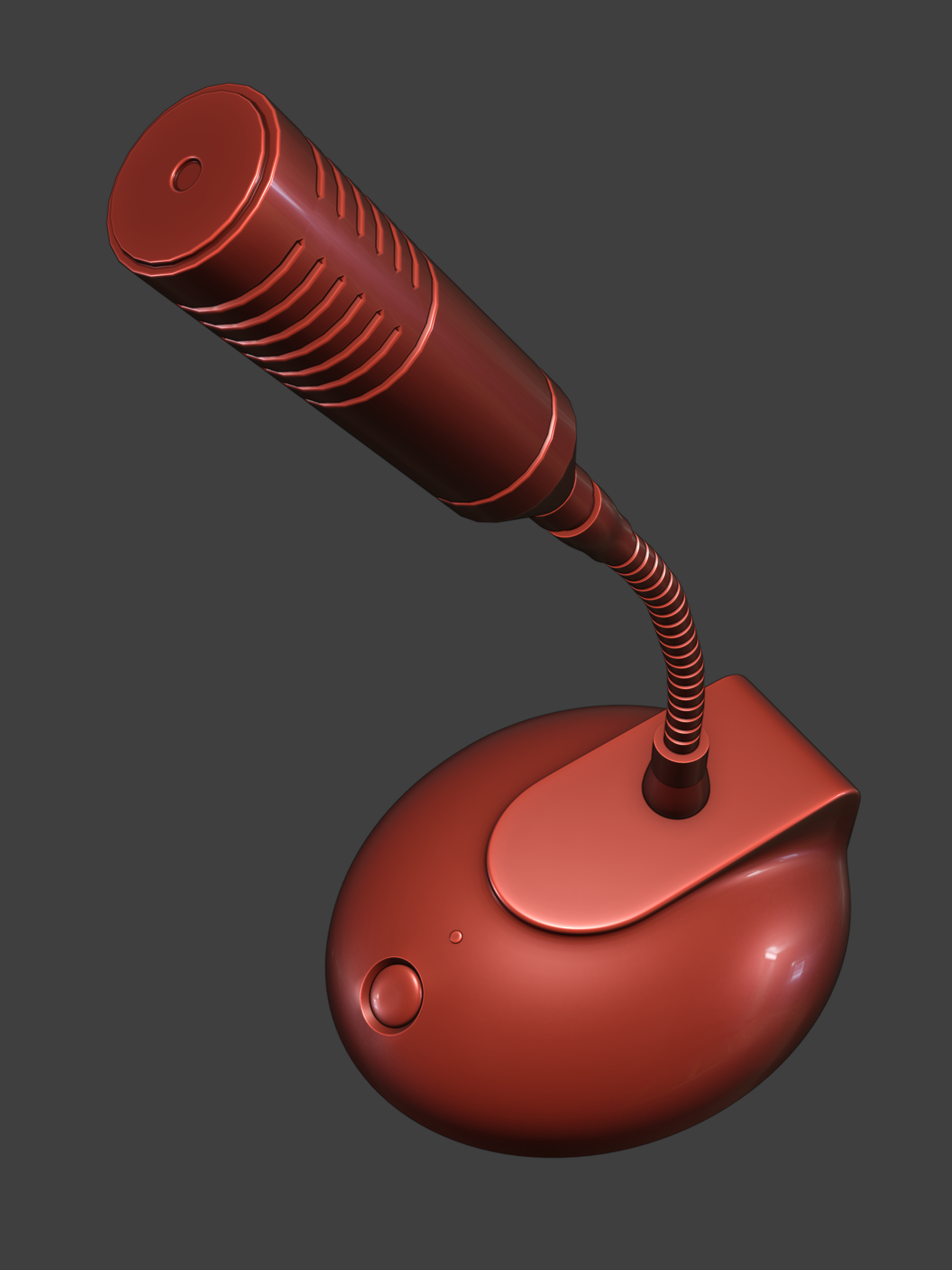 Overall
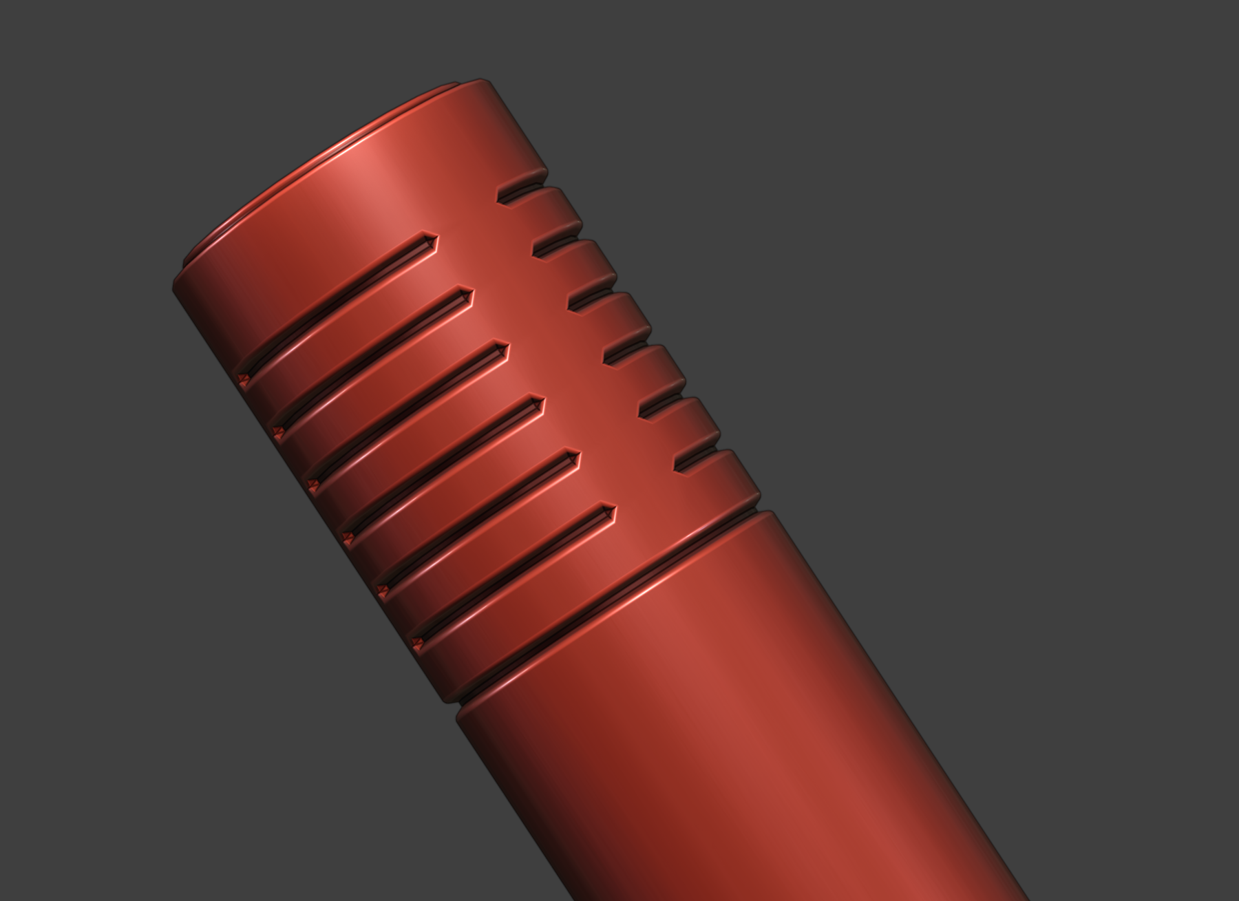 Head slits
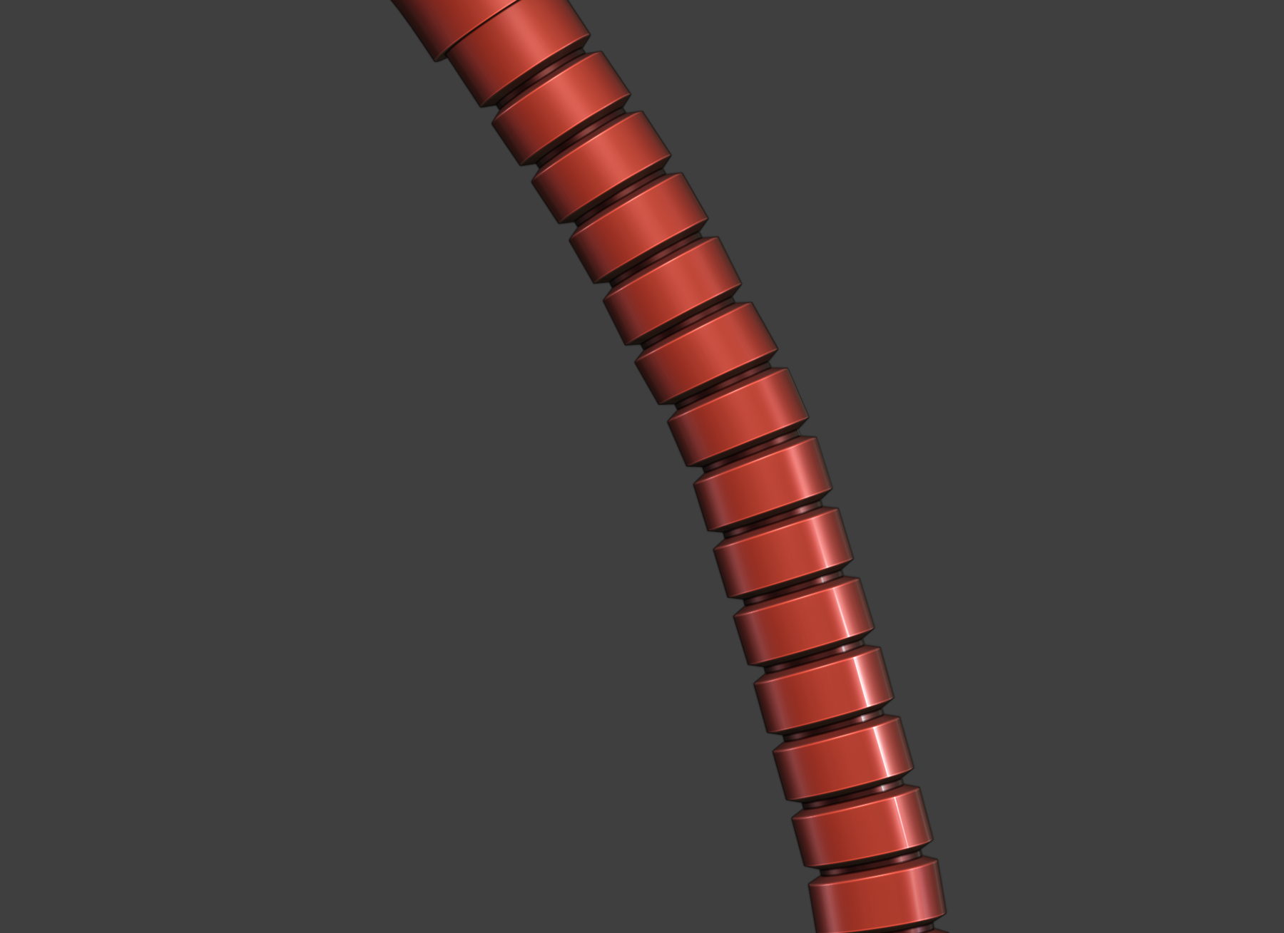 Neck bellows
6.2 Junction Finish
Available presets are:
- Standard: Grid Fill / Sharp
- Rounded: Grid Fill / Arc
- Stable: Cutoff / Sharp
- Custom: uses detailed junction settings
Expand Adjust Junctions to access:
- Intersection Method
- Inner Miter
- Spread
- Refine T-Junctions
- Vertex Search Radius
- Connection Tolerance
Corrections are applied to supported configurations. PLD does not guarantee all-quad topology, identical results for arbitrary inputs, or automatic repair of every possible intersection or shading issue.
Very acute configurations, including angles below 20°, may require manual adjustment.
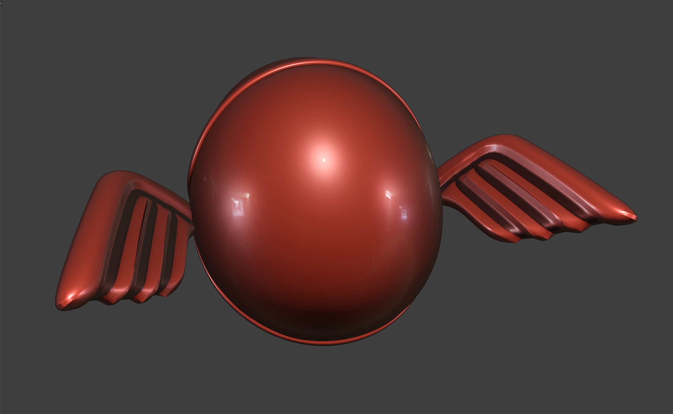 Overall
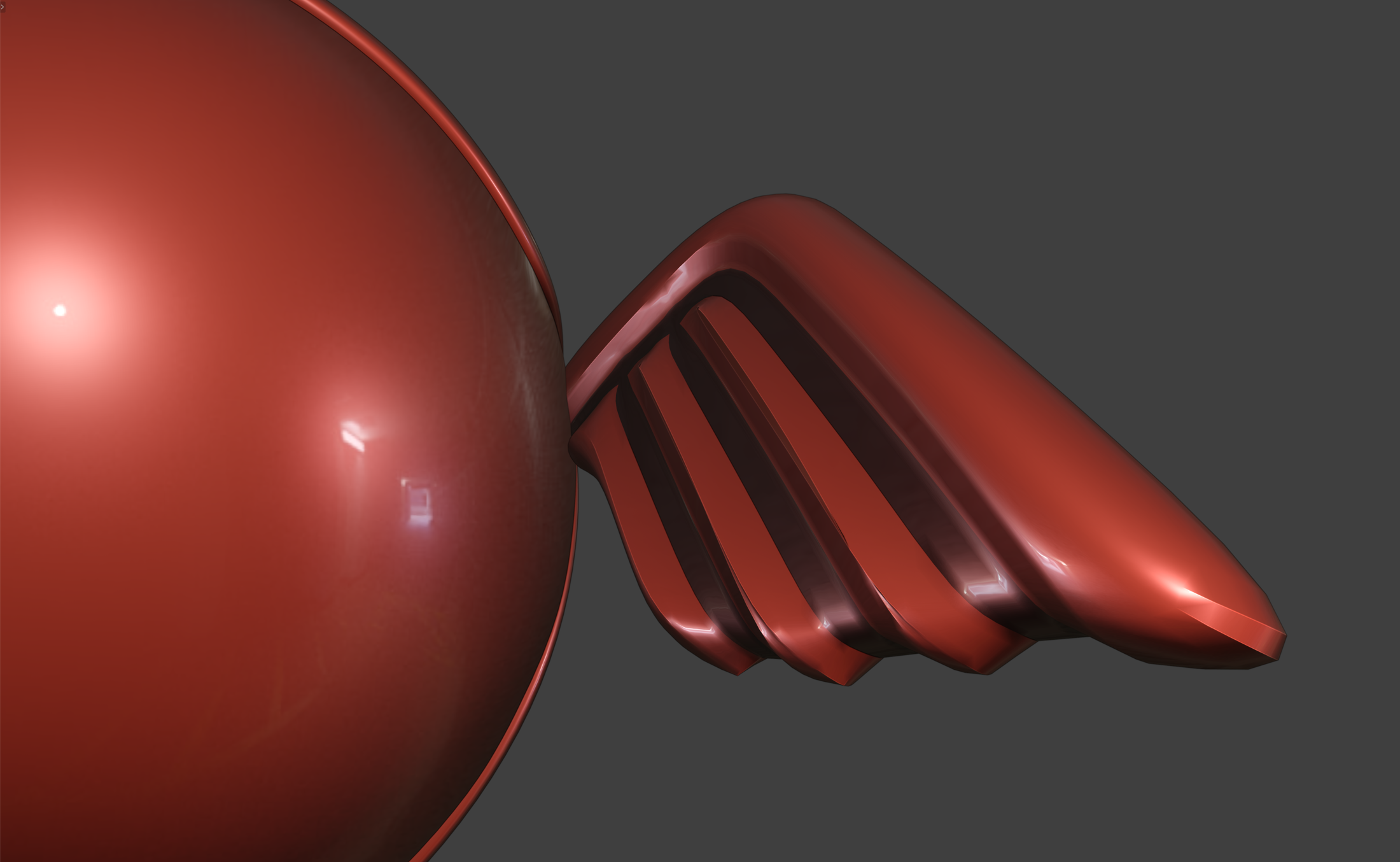 Groove detail
6.3 Finishing
Darken Groove Bottom (Panel Lining)
Assigns a dark material to the groove floor. View it in Material Preview or rendering.
Rim Bevel Weight
Writes PLD's dedicated pld_rim_weight edge attribute at the surface-to-wall boundary. This is separate from Blender's standard bevel_weight_edge.
Inherit Original Smoothing Settings
Copies supported smoothing and normal-adjustment modifiers from the source.
Auto Weighted Normal
Places Weighted Normal last with Keep Sharp enabled. An existing suitable Weighted Normal may be reused. Disabling this option removes only the modifier automatically added by PLD.
Inherit Original Bevel Settings
Copies supported edge/weight-limited Bevel modifiers from the source.
Inherit Original Mirror Settings
Copies Mirror modifiers to the result. Edges running along the Mirror center plane may not be processable before applying the Mirror.
Inherit Original Subdivision Settings
Copies Subdivision Surface settings to the result. PLD does not automatically apply the source Subdivision.
Line Turn Threshold
0–180°, default 30°. Lower values retain harder line turns; higher values allow smoother joins.
Surface Fold Threshold
0–180°, default 180°. Lower values retain folds more strongly where surface folding dominates the line turn.
Original crease-derived edges are excluded from these threshold adjustments.
6.4 Advanced Settings
Live Preview
When enabled, settings changes update the result automatically. Adjusting only Rim Rounding Width or Rounding Segments normally updates the modifiers without rebuilding the groove mesh. Missing required attributes or other conditions can trigger a full rebuild. Toggling Round Rim or changing the groove shape also rebuilds the result.
When disabled, automatic updates are suspended. Make several adjustments, then click Update Preview to apply them together. Try this workflow when updating the model after every adjustment interrupts your work.
Bottom Detection Width
Controls the region treated as the groove floor at complex intersections.
Clamp Overlap
Limits overlap during groove generation. This is a different processing stage from overlap limiting in the managed rounding Bevel and does not mean all intersections are eliminated.
Loop Slide
Controls loop-slide behavior during the underlying bevel operation.
Custom Bottom Material
Specifies a custom groove-floor material when bottom darkening is enabled.
7. Presets
PLD settings can be stored as presets in the current .blend Scene. Presets are not automatically shared with other .blend files.
Available operations are:
- Save New — save the current values as a new preset
- Apply — copy a saved preset to the current PLD result
- Overwrite — replace the selected preset with current values
- Delete — delete the selected preset
Rim rounding on/off, rounding width, and rounding segments are included in presets.
When saving a new preset, you can choose whether to include the custom bottom material.
PLD retains its 2.x preset/save identifiers, but automatic migration of PLD 1.x or PLD-E settings is not guaranteed.
8. Troubleshooting and Known Limitations
Rounding collapses or tiny faces appear
Extremely short edges or densely packed connections can produce collapsed rounding or very small faces.
Clean up the input edge layout and reduce Groove Width and/or 「フチの丸め幅」 — Rim Rounding Width.
PLD does not automatically merge these cases.
A groove passes through a thin part
Groove Depth may exceed the available thickness. Reduce the depth and inspect the back side.
Subdivision changes the original curvature
Groove creases can change the subdivided shape. PLD does not automatically apply the source Subdivision.
If necessary, make a separate copy of the source and apply Subdivision yourself before using PLD.
Stored edges cannot be reselected
The source topology may have changed since the selection was recorded. Check the selection again after changing the source mesh.
An edge along the Mirror center plane cannot be processed
Such edges may require the Mirror modifier to be applied before creating the groove.
Complex intersections or grooves near folds produce unwanted geometry
PLD includes corrections for T-junctions, intersections, acute configurations, and other supported cases, but it is not an automatic repair system for every possible mesh intersection or shading condition.
Intermediate crease values
Examples retaining original intermediate crease values such as 0.3 or 0.7 have been verified. However, exact propagation of the same intermediate value onto newly generated bevel edges is not guaranteed.
The current Geometry Nodes crease supplementation uses 0 or 1, rather than reproducing arbitrary intermediate crease values.
Can PLD output be used for 3D printing?
PLD does not provide unconditional 3D-print readiness.
Before export, inspect the evaluated/output mesh after applying any modifiers required for your workflow. Check thickness, intersections, manifold state, and other requirements for your printing process.
Validation Scope
Tests using the distribution ZIP in Blender 5.1.2 on macOS covered T/cross/enclosed selections, 0°/180° thresholds, rounding toggles, modifier order, and presets. These checks do not guarantee results for every user model.
Reporting a Problem
When reporting a reproducible issue, please include as much of the following information as possible:
- Blender version
- Operating system
- PLD version
- Steps required to reproduce the issue
- Relevant PLD settings
- Screenshots showing the input and result
- A minimal reproducible
.blendfile, if you are able to share one
A simplified .blend containing only the geometry required to reproduce the problem is especially useful when the original project cannot be shared.
Panel Line Designer (PLD) 2.0.21 — Public Trial
RENDA - TOKUGAWA ELECTRONICS.